
October 21, 2024
By Kevin Hyland, Principal Engineer, Fire Resistance and Containment
Various methods exist to design and construct firewalls to separate fire areas while maintaining structural stability in the event of a fire. One design method is commonly referred to as an area separation wall, which is permitted by model building codes. These are unique wall assemblies intended for use as townhouses or duplex separations designed following requirements in the International Residential Code (IRC), Section R302, and the International Building Code (IBC), Section 706.
The following information can also be found in the BXUV Info Guide on fire resistance ratings under “Gypsum Area Separation Wall Designs.”
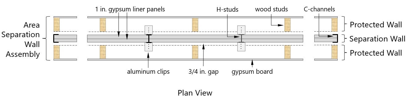
Separation Wall Section and Protected Wall Section
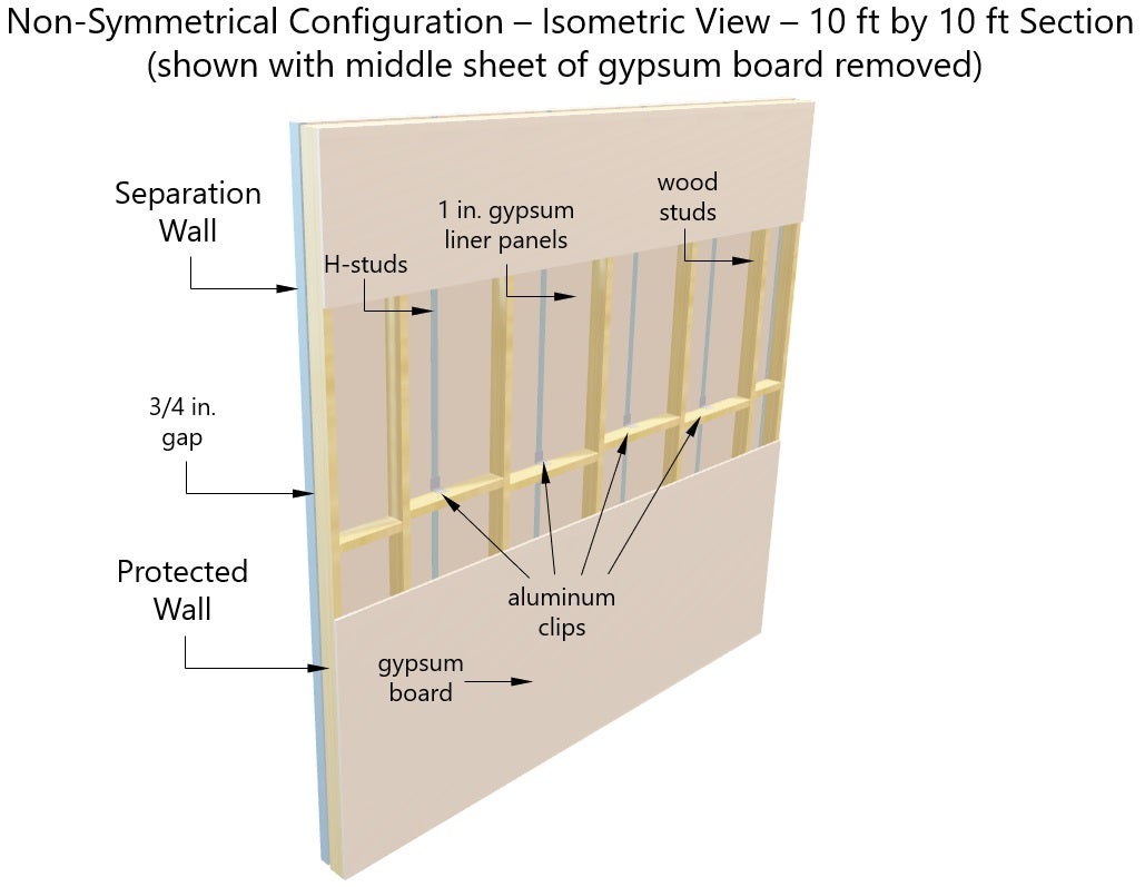
The Gypsum Area Separation Wall designs (assemblies) consist of two basic sections: a Separation Wall section (also referred to as a “Common Wall”) and a Protected Wall section (also referred to as a “Flanking Wall”) on one or both sides of the Separation Wall section, as shown in the figure below. The Separation Wall section is braced by the Protected Wall section(s) with aluminum breakaway (attachment) clips, and the wall sections are separated by a minimum of 3/4in. gap.”
The most common Separation Wall section consists of two layers of 1in. thick gypsum liner panels, secured with horizontal and vertical C-channels (C-runners) at the perimeter and vertical H-studs between panels in the field. Other than its own dead weight, the separation Wall section is non-load bearing. The Separation Wall section provides the majority of the fire performance of the overall wall assembly’s assigned fire rating. However, the Separation Wall section alone, without the 3/4 in. gap, does not meet the requirements of UL 263, the Standard for Fire Tests of Building Construction and Materials. Also, when loaded in the fire test to simulate heights greater than 10 ft, the Separation Wall section would not have the inherent structural stability to support the added dead load without bracing from the adjacent framing of the Protected Wall section(s).
The Protected Wall section consists of wood stud or steel stud framing spaced a minimum of 3/4in. from the Separation Wall section, with one layer of gypsum panels or other various facings attached to the outside of the framing. The Protected Wall section can be load-bearing or non-load-bearing. The Protected Wall section and aluminum breakaway clip combination provide structural stability and additional temperature transmission protection for the Separation Wall section. By itself, the Protected Wall section does not meet the requirements of UL 263.
The Separation Wall and the Protected Wall section(s) form the overall Gypsum Area Separation Wall Assembly, and only when constructed together as specified in the individual designs are all the requirements of UL 263 met for the assigned assembly rating.
Symmetrical Configuration and Non-Symmetrical Configuration
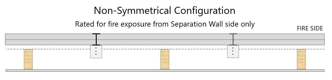
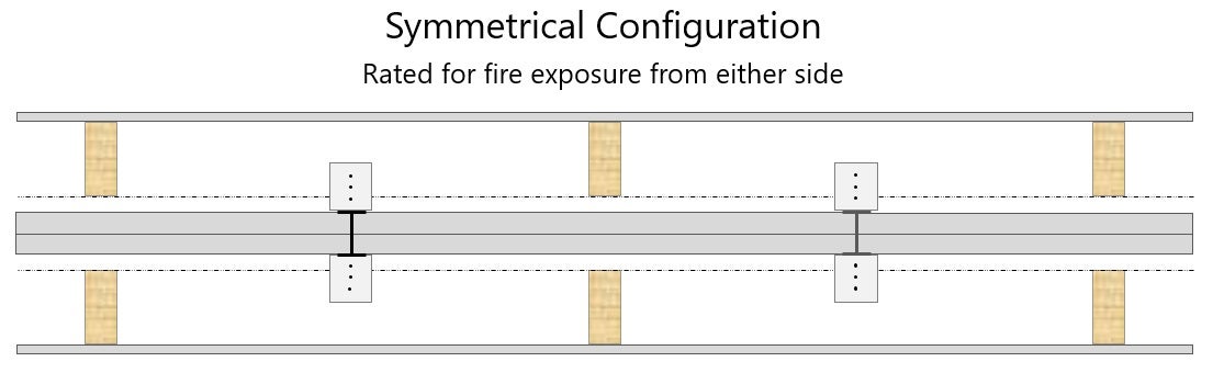
The Gypsum Area Separation Wall designs typically include two configurations: a symmetrical configuration with a Protected Wall section on both sides of the Separation Wall section, and a non-symmetrical configuration with a Protected Wall section on only one side of the Separation Wall section.
When constructed in the non-symmetrical configuration, the assembly is rated for fire exposure from the Separation Wall side only, as shown in the figure below. When exposed to fire on the Separation Wall side, the Separation Wall section resists the passage of fire while the Protected Wall section provides stability and additional resistance to heat transfer.
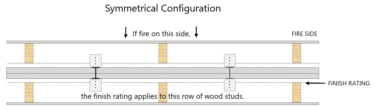
When constructed in the symmetrical configuration, the assembly is rated for fire exposure from either side, as shown in the figure below. When exposed to fire, the Protected Wall section on the fire side is designed to break away from the Separation Wall section and collapse, leaving the Separation Wall section in place and the Protected Wall section on the non-fire side.
Finish Rating
The heading of the Gypsum Area Separation Wall designs typically lists a finish rating of 120 minutes. As mentioned earlier in this Guide, the finish rating is defined as the time at which the wood stud reaches an average temperature rise of 250°F or an individual temperature rise of 325°F as measured on the plane of the wood nearest the fire.
As depicted in the figure below, the finish rating applies to the face of the wood stud on the Protected Wall section on the side opposite of the fire.
The finish rating is supplementary information, not a substitute for the assembly rating.
Aluminum Breakaway Clip Spacing
The Separation Wall and Protected Wall sections (s) are connected with aluminum breakaway clips and separated by a minimum 3/4 in. gap. One leg of the breakaway clip is attached to the H studs of the Separation Wall section and the other leg is attached to the wood or steel framing of the Protected Wall section, as shown in the figure below. The breakaway clip spacing in the individual designs will vary based on the overall height of the wall.
Alternates to the Gypsum Panels on the Protected Wall Section
The Gypsum Area Separation Wall designs may include alternate facings such as plywood or oriented strand board (OSB) on the studs of the Protection Wall section. Also, insulation in the stud cavities or gypsum panel batten strips attached over the H studs may be allowable.
Refer to the individual designs for any allowable alternates and their installation requirements.
X
Stay informed
Actionable insights on the topics you choose, delivered directly to your inbox.
Please wait…
Characters remaining